- Shop
-
- Brand
- Special Promotions
- About Us
- Contact Us
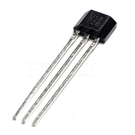
U18/US1881/OH188/188 Hall Effect Sensor COM23, R32
$ 96.24
DescriptionThe US1881 is a bipolar Hall effect sensor IC fabricated from mixed signal CMOS technology and its output voltage varies in response to a magnetic field .The design, specifications and performance have been optimized for commutation applications in 5V and 12V brushless DC motors.Features:Wide operating voltage range from 3.5V to 24VChopper stabilized amplifier stageOptimized for BDC motor applications High magnetic sensitivity – Multi-purposeLow current consumptionTemperature compensationCMOS TechnologyApplications:Solid state switchBrushless DC motor commutationSpeed sensingLinear position sensingAngular position sensingCurrent sensingProximity detectionGetting started with theThis project uses a Hall effect sensor to detect the presence of a magnet. Whenever a magnet moves past this sensor, it can detect it. This sensor can be used to do a lot of different things. For instance, if we need to detect a door closing; then we simply have to attach a magnet to the door and a hall sensor to the frame of the door. Whenever the door closes, the magnet is placed near the hall effect sensor and we are able to detect that the door has been closed.How Does It Work? The Hall effect sensor works on the principle of the Hall effect, which states that whenever a magnetic field is applied in a direction perpendicular to the flow of electric current in a conductor, a potential difference is induced. This voltage can be used to detect whether the sensor is in the proximity of a magnet or not. The Arduino can detect this voltage change through its interrupt pin and determine whether the magnet is near the sensor or not. The basic working of the Arduino Hall effect sensor is shown in the picture below. Hardware requiredArduino UnoBreadboardU18/US1881Hall effect sensors have three pins: VCC(5V), GND, and Vout(Signal). The pinout of a Hall effect sensor is as shown belowConnecting the HardwareInterfacing the Hall effect sensor with Arduino is really simple. The VCC of the sensor is connected to Arduino’s 5V power pin. The GND of the sensor is connected to the GND pin on the Arduino. The Vout or signal pin of the Hall effect sensor is connected to the Arduino’s interrupt pin (digital pin 2). Furthermore, a 10K resistor is connected between the VCC and Vout pins of the Hall effect sensor. This is done to pull the output of the Hall effect sensor to 5V. The connections are done as shown belowUploading the Code and Open the Serial monitorAfter you finish hooking up the Hall effect sensor to your Arduino, you need to upload the code to the board and test it.Download code here: Arduino Hall effect sensorWhenever the Hall effect sensor detects a magnet, it outputs a HIGH (5V) voltage to its Vout pin. The interrupt pin of the Arduino that is connected to Vout detects this rising (HIGH) voltage through the function: magnet_detect. The serial monitor prints “detect” whenever a magnet is brought close to the sensor.
Related Products
-
Bonafide Edibles – Watermelon Fruit Cubes 300MG THC $ 12.03Select options This product has multiple variants. The options may be chosen on the product pageQuick View
-
BANG Men’s Performance Gummies – Blue Raspberry $ 15.83Select options This product has multiple variants. The options may be chosen on the product pageQuick View
-
Bonafide Edibles – Blue Raspberry Fruit Cubes 300MG THC $ 12.03Select options This product has multiple variants. The options may be chosen on the product pageQuick View
-
BLISS – Infused Gummies Green Apple 250MG $ 13.93Select options This product has multiple variants. The options may be chosen on the product pageQuick View
-
-